Welcome back to the second entry in the series: How not to build an observatory. Previously we covered the differences between observatory types, DIY vs buying , and getting the first mechanical part of the dome done: the motorised ring. In part 2 we’re going to cover the dome design, construction, and building the shutter. And of course covering the biggest mistakes I made while building Wonky, so let’s begin!
When building an observatory dome there are a few things to take into consideration: The size and rotation (which we already covered), shutter type, shutter width and length, shutter operation, supports, power, and cladding. It sounds like a lot because it really is!
The Shutter
Like last time we had to make a big decision in our design, there are two main options: The first is a roll over shutter, which does exactly as it sounds: the shutter rolls back over the top of the dome to reveal the slot. And the second is a dual shutter design, where two large doors slide horizontally open and closed to reveal the slot. Of course there are also a whole bunch of other variants you can play with, but in our design it came down to the two options. And, once again each design comes with its own benefits and drawbacks.

Credit: Pulsar Observatories
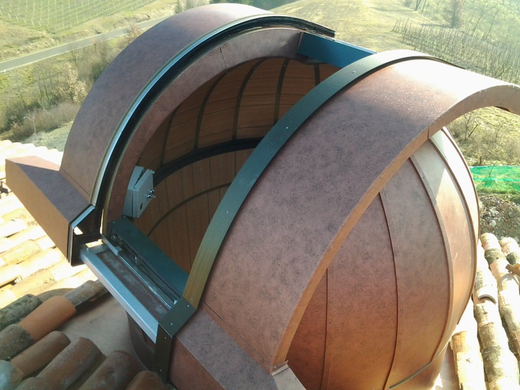
Roll over shutters are a popular design as they are relatively straight forward, and are generally easy to make weatherproof. By fixing the roller bearings under an angle we can ensure that the design prevents rain from getting in, and given that the shutter hugs the dome we can also ensure that wind won’t have a big impact on the operation of the shutter. However, the main drawback with the roll over shutter is that you have more limited space to work with. To ensure a good view of the zenith you’ll need to ensure that the slot opens past the top of the dome, which also impacts the size of the shutter that you can use (given the shutter curve will collide with the base), and thus impacts the length of the slot. This consideration can also limit the amount of horizon you can see from your scope. You’ll need to first figure out how far past the zenith you’ll want your scope to go, and then your shutter length should be the remaining length minus some buffer for weather proofing and bearings etc. You’ll want to measure, check, and re-check this. As I had to redo this step twice.
Credit: Gambato Observatories
The second option here is the dual shutter design. The main advantage of the dual shutter is that you can theoretically make the slot length as long as you need, as the length won’t restrict the room the shutter has to operate with. Making it more suited to places that have an open horizon. However there are two, minor, drawbacks here compared to the rollover: the mechanics of it and the weather proofing. Starting with the mechanics, you now have two moving parts instead of one. That might mean more materials, more limit switches, greater difficulty getting them to align, and additional areas for potential failure. As for the weatherproofing side, you also now have a join running right down the middle of where your telescope is sitting, so you’ll need to make sure that the channels running down the join are designed for heavy rainfall. The other potential issue with weatherproofing is how windy your chosen location gets, as you’ll now have two giant sails on the side of your observatory, and we certainly don’t want the dome going on its own journey.
So that was a lot of information to digest. But really it comes down to this: Do you have clear unobstructed views to the horizon? And is your chosen location safe from strong winds? Well, maybe consider the dual shutter, especially if you’re ok with a little extra weatherproofing. Otherwise you might be better off choosing a shutter, like I did. Although my location has great views down to the horizon it can unfortunately be prone to some high winds.
Finally, once we’ve chosen our design and shutter length, we chose our width. Given the size of our dome (3 meters if you remember from our last entry) we actually have a fair amount of play with how wide the shutter is. You can find some good advice online for this, as factors like focal length and telescope/mirror/lense size can affect it, but generally 1 meter is considered pretty good and more than enough for the RC12 I have sitting in the observatory right now.
And that’s it, right? We can get started? Well, not quite. Now we need to design our frame with the above in mind
The Frame
Now that we’ve figured out how our shutter will work, and what dimensions we require, we need to design our frame with those considerations in mind. Let’s start with what I’ll call our base radius. Given the diameter of our design in part 1 was 3 meters you’d think that would be straight forward right? Just roll some steel at a 1500mm radius (btw we’re swapping to mm now because things are going to get gnarly) and start welding and cutting? Well, not quite. Remember that although our ring has a radius of 1.5 meters we also opted for using top rollers to secure the ring to the base. This means we can’t just measure from the ring itself, we’ll need to weld supports at a right angle to the ring, increasing the radius of our dome.

With this in mind we’ve added a 75mm buffer, now making the radius 1575mm. Can we start rolling yet? Nope, of course not. We need to figure out how many supports we’re using, how long they need to be, using the following handy diagram I borrowed from Stargazers Lounge:
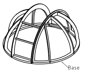
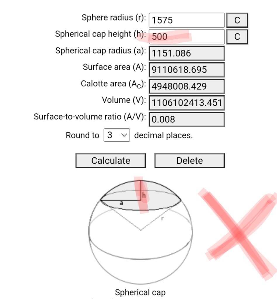
To me that looks like 6 short lengths for the supports, and two for the shutter. So we can start now, yes? Nope! Notice how the slot is different to the supports? We now need to calculate for the slot as it will actually have a different radius, given that it cuts into the dome. Remember our slot width? 1000mm right? Great. The next step is using a spherical cap calculation to figure out what this radius should be. We’re taking our radius of 1575mm and capping into it for 500mm
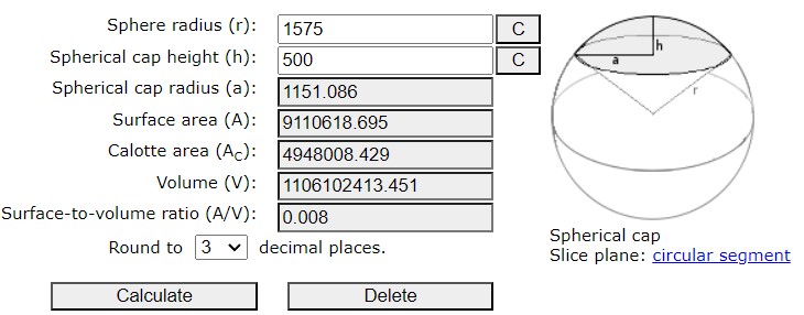
Done. 1151mm is the radius of our shutter section. Or is it? Some of you may have noticed something funky, but for now let’s continue on, like I did. Next step: what materials are we using? Strap steel? Angle? Square? Pipe? Honestly, whatever you think may work. For most of the frame I opted for some 20x20mm square tube steel. It’s relatively light, durable, and rolls well. However, for the slot and the runner for our shutter, I wanted to try something else to kill two birds with one stone by choosing some angle steel. Two good large pieces of 50x50mm angle steel should do the trick. Thick too, as that shutter will be doing some reps. So, that’s 2x 50x50mm angle steel, at a radius of 1151, which gives us a length of 3742 (using (2 x PI x r)/2 )
Then, using that handy diagram above, it’s time to calculate the length of our supports. Starting with the spacing, I used an engineering drawing program to measure a lot of this out (I believe it was On Shape?). To ensure adequate support of the two shutters we want our supports to be evenly spaced, starting with two at 90 degree angles from the slot, then four more spaced between the middle 90 degree supports, and where the shutter slot intersects the ring.

This got me the horizontal length of each set of the supports: 960mm and 1075mm. I know we’re doing a lot of math right now, but just push through with me, ok? Because next up we need to measure how long these supports are. Knowing the horizontal distance we can now draw these out from a side on view, to get the vertical distance and measure the final length with an arc calculator.
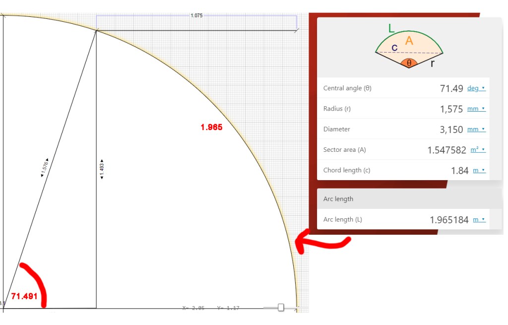
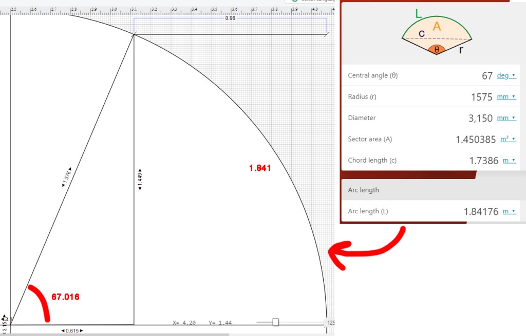
So now we have six pieces of 20x20mm square tube at 1575mm radius, two are 1965mm long and four are 1841 long. Are we done yet? Again, nope. We’re forgetting the steel for the shutter. Which I just went with the same length that we calculated for our slot: 3742mm. This brings our order to:
At radius 1575
4 x 1841 lengths SHS 20 x 20
2 x 1965 lengths SHS 20 x 20
At radius 1191
2 x 3742 lengths Angle 50 x 50
2 x 3742 lengths SHS 20 x 20
NOW are we ready? Why, yes. At this step I got hold of my good mate Ash again (you remember him, right? We ran our designs past him and he put us onto the awesome motor) and I asked him about rolling steel. He put me on to a group he’d used before, that do great work. And he asks me: inside or outside diameter for these measurements?
Oh no, I forgot about that part. You might remember that we gave our ring 75mm clearance, well turns out that was to allow space for 20mm steel. Which would make our calculations outside radius? I check the math, it seems right but I add a little extra steel just in case things go pear shaped. The order is sent off, and we wait….
Picking Up The Steel
After some long delays due to steel shortages and COVID, I finally get the call: the steel is ready. So I hire a ute, pick up the steel, and deliver it to the farm. I am SO excited.

So optimistic, and so naïve
It’s time to get cracking again. I lay out the steel, and my brother and I start preparing to weld, but wait…these shutter pieces are awfully small, is that right? I start measuring and calculating and checking the invoice like a mad man. Everything checks out, but why are the pieces so small? My math was dead on, unless it wasn’t? So I go back to the spherical cap calculation, and to my horror I notice a mistake, I calculated it from the outside in, and not the inside out
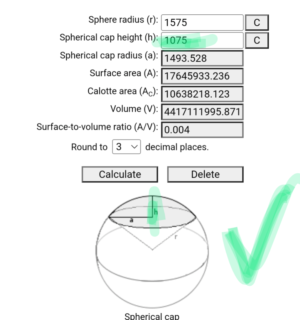
That’s about a 400mm difference in radius, talk about a set back! So I start wondering, can I just use a massive shutter instead? What else can I do? Ash says the steel place has offered to reroll the pieces as a priority if I get the right measurements, but they’ve never rolled steel back out before so they can’t give any guarantee that it’ll work. I figure it’s worth a shot. This time I triple check my measurements and do a little paper prototype

Very hi-tech
It’s good. In a mad dash I borrow a car and trailer from my brother, return the steel two hours away to the steel place, wait a few days, drive out after work and pick it up again. On arrival the engineers say they did their best, but unfortunately rolling the steel back out has twisted it. It’s disappointing, but I risked it so I wouldn’t have to pay for more steel.

It’s still good, it’s still good…
I’m sure we can make it work. I stop at my place overnight, and convince myself that the twisted steel won’t be an issue. The next morning I get ready to go, but oh no. Someone decided to slash my tyres. And not just the car tyres, the trailer tyres too.
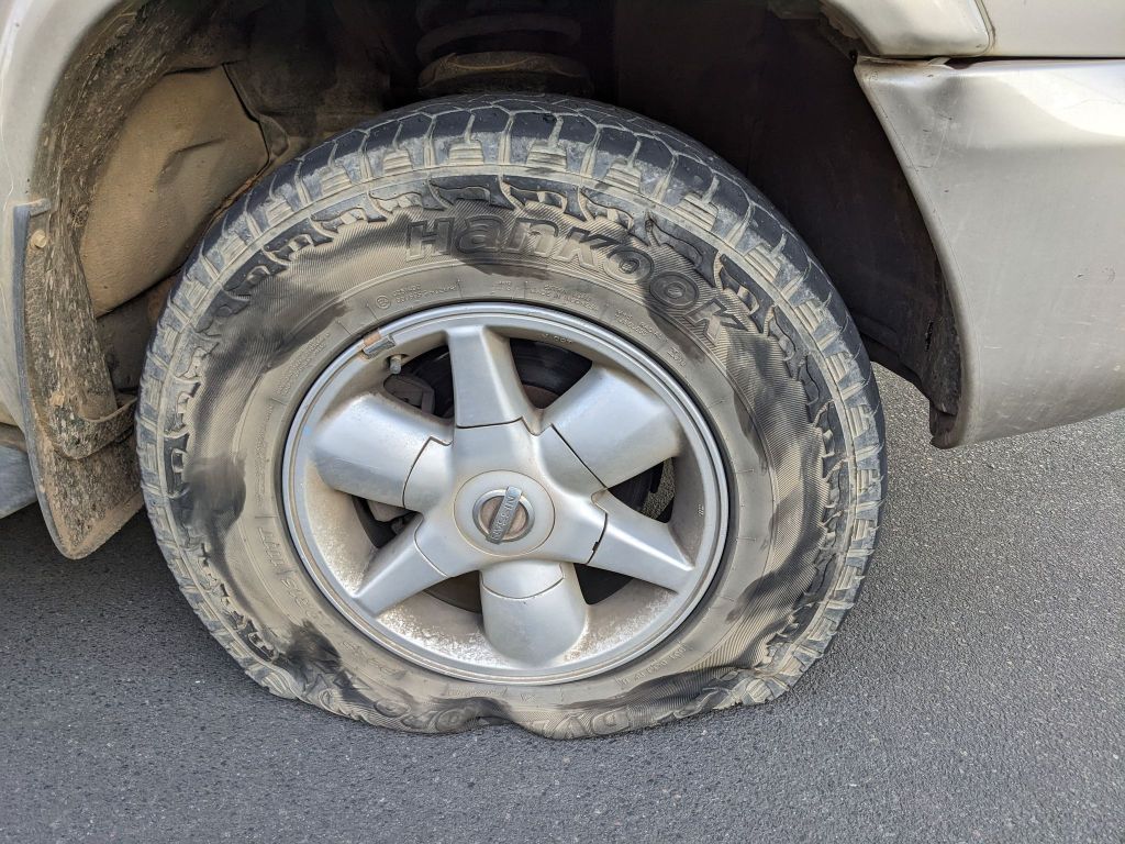
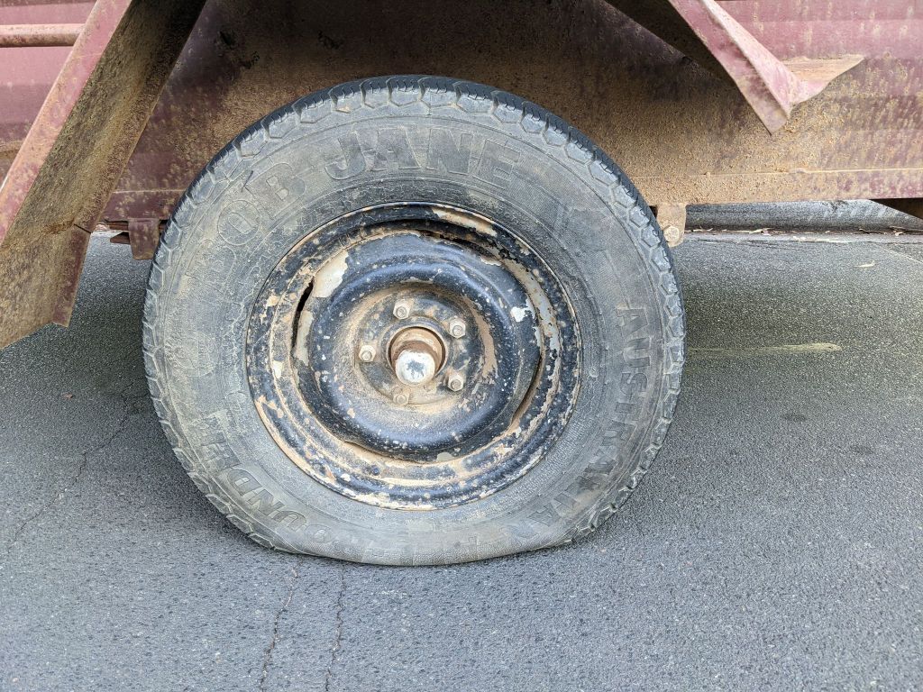
Well, can’t say they weren’t thorough…
First the miscalculation, then the twisted steel, now this. I’m starting to think that the universe doesn’t want this observatory to be built (despite the first two things being entirely my fault). After some spare tyres and running around I finally get back on the road and return the steel, car, and trailer to the farm. Time to assess how twisted these beams are, and what we can do to fix it.
Fixing My Mistakes…kind of
There I was, I had a bunch of great plans and ideas, but one simple mistake lead to a bunch of twisted steel. Well, no point being upset, I’m doing this on a budget and I gotta work with what I got. My brother and I assess the pieces of steel and we find there’s one thing on our side: due to how the rollers price the steel I have more angle steel than I need. My brother suggests cutting the straighter parts out, recombining, then using an oxy torch to straighten out whatever is left. It’s a solid plan, so we go with it. We start with welding the shutter slot pieces together with their supports, and welding some extra steel supports to keep it in shape (that we’ll remove later).
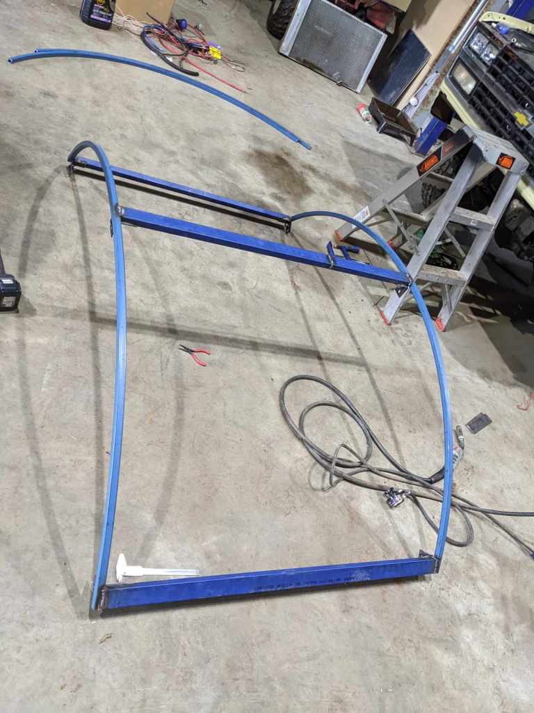
Not that bad, if you ignore the far end of it…
It’s not the worst. A little lopsided sure, but once we mount it on the ring we can nudge it around and use tensioning straps while we weld the supports in. It takes us a long time, and there’s a lot of cranking of straps, heating metal, hammering, swearing, and we also realise that the misshapen ring is throwing other parts out, leading to more swearing and hammering. But in the end we finally have something that looks like a dome. And you could say that this is where Wonky got its wonk.
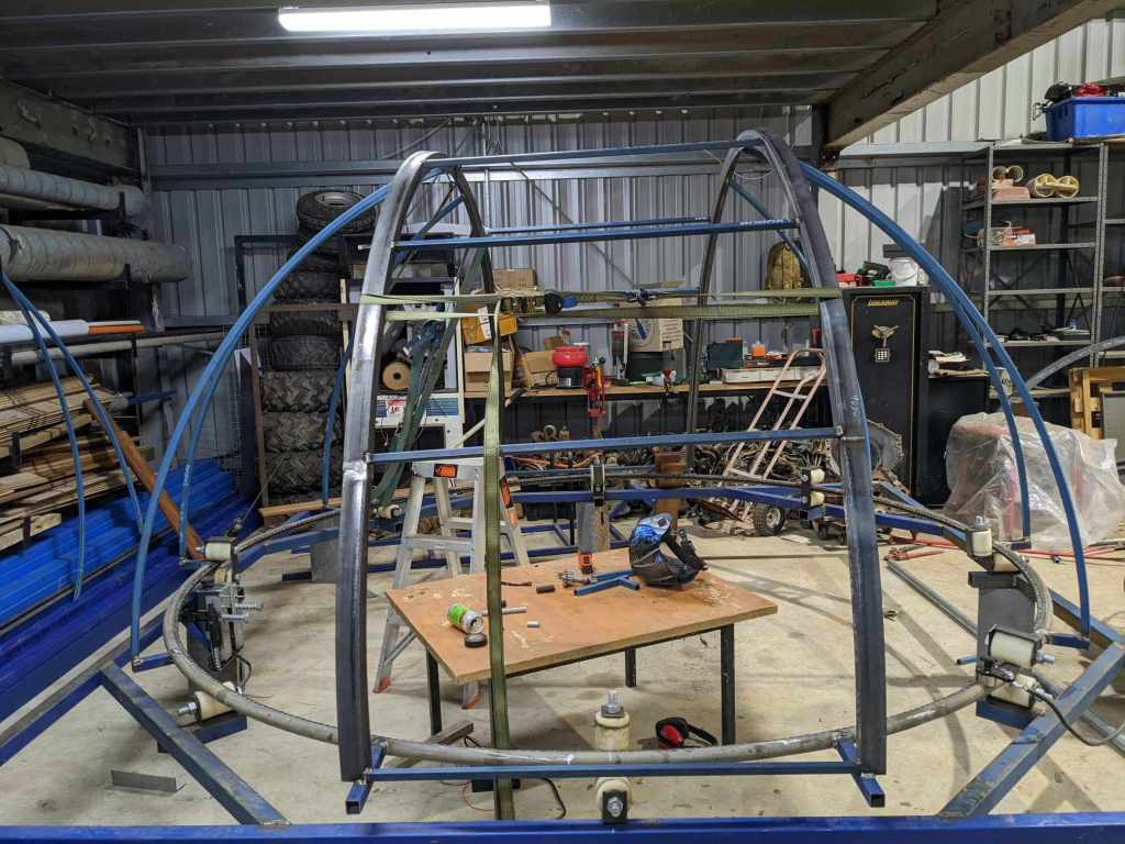
It looks functional…enough
Oh Yeah, The Shutter
In all the excitement of fixing my mistake there was yet another thing I didn’t properly measure out, the shutter mechanism itself. From this point on everything gets a little ad-hoc. I incorrectly measured the length of the slot, twice, forcing me to re-cut and re-weld certain parts. And remember how I used tensioning straps to hold things together earlier? Well, cutting those welds, that were made under tension, does make for some surprises. Then I put together the shutter and weld it, but remember how I got the radius wrong for the shutter pieces? Well I forgot to send in the shutter pieces for rerolling. It’s a little short in the radius, so I use a tried and tested way of reshaping steel: jumping on it.
Once again, it looks functional enough
However, with all that pain out of the way we can focus on the mechanics of it again. To allow the shutter to move along the angle steel I opted for twelve threaded bearings, on three supports (front, middle, and back) that I weld to the underside of the shutter. And finally I start getting things right again as the bearings glide, somewhat, smoothly over the misshapen slot. Although plenty of room between the bearings needs to be added, given the twisted steel in places.
Yup, definitely functional
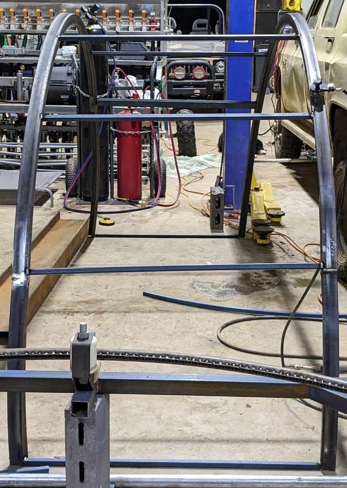
For the mechanics I decided to use a chain to drive it as well. Pulsar domes use a plastic chain through dual sets of pulleys for their shutters, so I decided to do the same but with steel chain. I order some pulleys online to handle the chain, build some brackets, and try to run the chain through. But oh no, yet another mistake: the pulley is only wide enough at the edge, because the trench tapers in the chain can’t sit easily in the pulley. At this point in the process I am exceedingly impatient, so instead of trying to find a new pulley design that might work I grab the heat gun, and heat each pulley while I roll the chain through it. Come hell or high water these pulleys will work, and they do, although they do look like they’ve seen better days.
Now all that’s needed to complete the mechanism is a motor to drive it. My brother suggests a wiper motor, and points out that my old Nissan Gazelle (former daily turned one day drift car) is gathering rust at the farm. In a weird way it’s kind of thematic, using something from my old hobby to enable my new one. And it works the charm.
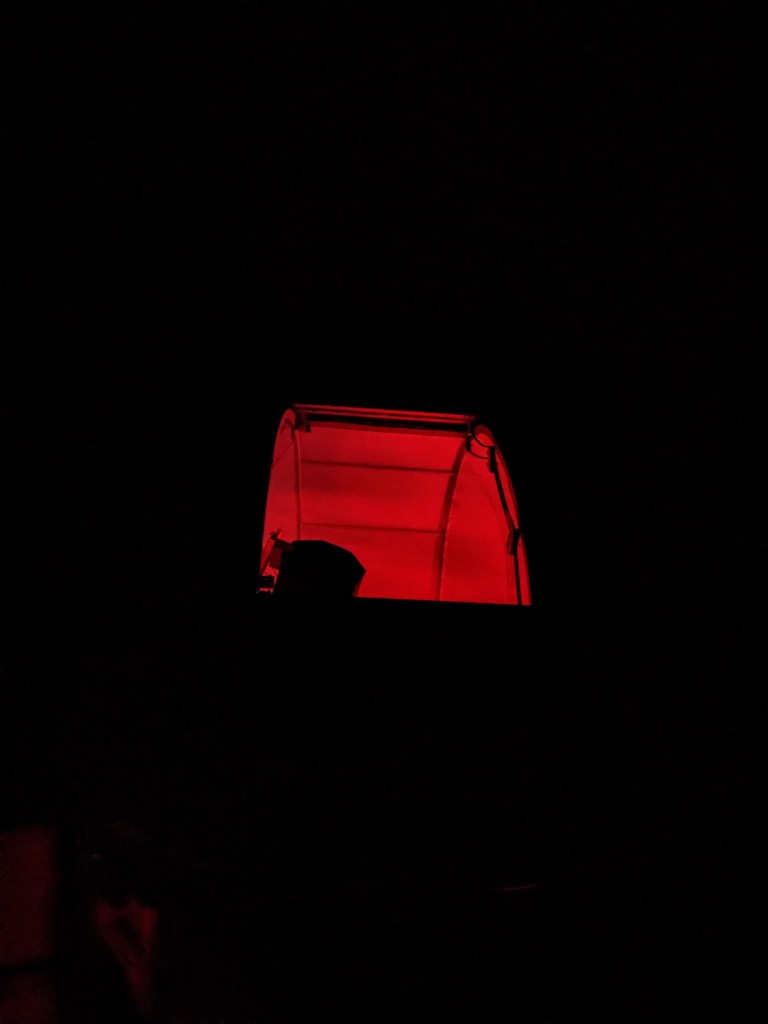
Smooth as butter
I added the electronics and now we have a functioning observatory frame. And I cannot describe the relief I felt at this time.
WONKY LIVES
Lessons Learned
This phase of construction was an absolute saga, and it all began with one simple mistake. So let’s go through the lessons learned
- The slot calculation: The big one. The only advice I really have here is to triple check your calculations, and make sure that you read the diagrams of any online calculators that you use correctly. It may also help to do a paper prototype, like I did later, using the lengths you’ve calculated. If I had of done that I would have noticed the short slot radius before ordering the steel.
- The twisted steel: You can only ever roll steel further inwards, never outwards. Just don’t try it. Here I should have ate the cost and ordered new steel. It would have cost more but I would have saved many more hours in the long run.
- The steel in general: Honestly the 20×20 steel was fine. It’s still holding up to this day without warping or breaking. I would re-think the thick 50×50 angle though. It’s heavy and definitely overkill. I added around 120kgs of weight to the dome with the shutter steel alone. You could probably get away with smaller and/or thinner angle.
- Using a roll over shutter: Would definitely do it again if I had to. The mechanism overall was pretty straight forward, and without the twisted steel it would have been the easier part of this project. It’s also been quite weatherproof.
- The pulleys and chain driving it: This approach also worked well. However I definitely would have found some more appropriate pulleys. Possibly even fork out for some metal ones.
So that’s it! I hope you enjoyed the second part of this series. Again, a special thanks to my brother Callum for all his help with welding and construction, and to Ash for his help and guidance as well. In Part 3 we’ll look at how the dome was clad, weatherproofed, and put together on site. Until then, clear skies!

Leave a comment